Autogyro Trim Control
Bensen Autogyro Trim Control
![]()
Summer job at Bensen Aircraft, manufacturer of autogyro aircraft, in Raleigh, North Carolina.
 |
 |
Steve Hines’ 4th-year college summer job.
In 1967 two years before graduating from NC State, Steve Hines’ summer job was with Bensen Aircraft in Research & Development under the direction of Igor Bensen, pioneer in autogyro aircraft.
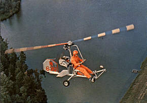
The assignment was to develop an in-flight trim control, to compensate for the diminishing weight of the fuel tank, on the front left, which causes the autogyro to gradually pitch up and roll to the right.
Before the summer was out, Steve had filled a notebook with technical ideas, notes, and photos of prototypes. The solution used a single cable (shown in red) to independently adjust the pitch and roll. Pulling the red cable made the rotor and the autogyro pitch up. Pulling the yellow cable made the red cable shift right and left, so that the red cable would pull in a different direction to affect the roll of the craft. The in-flight trim control was successfully test flown by Igor Bensen, in a B-8 Gyrocopter like that shown above.
|
The trim control is based on the geometry of an ellipse which can be drawn with a string attached at two points (the foci). The triangular frame swings around a pivot at the center of the circle, approximating an ellipse, within this angle. This allows the red cable to follow a path, between the two foci of the ellipse, without changing path length. The red cable pulls on the back of the rotor gimbal (above the view) from different angles which makes the rotor tilt left or right, and makes the autogyro bank left or right. |
The upper focus of the ellipse is the red cable’s attachment at the back of the gimbal (out of view). The lower focus is where the intermediate red cable contacts the upper roller. The movable roller swings in an arc, closely simulating a portion of an ellipse. |
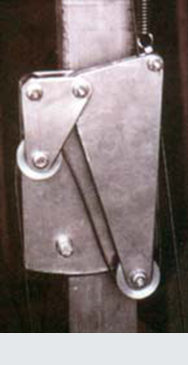
Regardless of how the roller swings left or right, the red cable maintains a constant path length between the foci of the ellipse. Further, pulling the red pitch-control cable, around the rollers, has no effect on the swing position of the lower roller. Therefore, there is complete independence between the two adjustments, both of which are controlled by the same red cable in different ways.
The lower ends of both the pitch-control cable (red) and the roll-control cable (yellow) are routed around pulleys to adjustment knobs at the pilot’s seat. The pitch-control knob is mounted on the side of the seat (so that turning the knob makes the autogyro pitch in the same direction that the knob is turned). The roll-control knob is mounted on the front of the seat, so that rotation of the knob makes the autogyro roll in the same direction that the knob is turned.
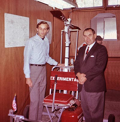
Steve Hines, left, with President Igor Bensen
This is not a product for sale, but is shown as an example of past engineering by Steve Hines.