Projected Auto-stereoscopic 3-D System
Projected Auto-Stereoscopic 3-D System
Large screen 3-D video for multiple viewers without the need for glasses.
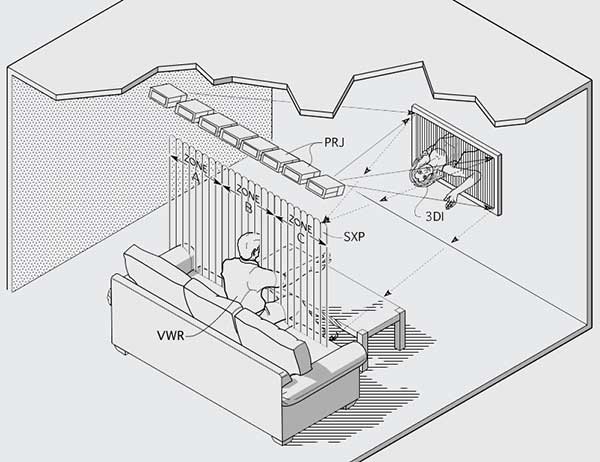
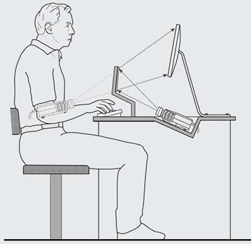
This technique projects video images onto a flat screen hanging on a wall, which forms viewing positons under each projector. A viewer at that distance will see the stereoscopic views with lateral motion parallax without needing 3-D glasses. This technique is ideal for 3-D presentaions at trade-shows.

All techniques described here avoid the bright reflected hot spot of the projector on the screen by shifting the projector vertically. In the illustration above, the hot spot would have occurred well above the screen’s position.
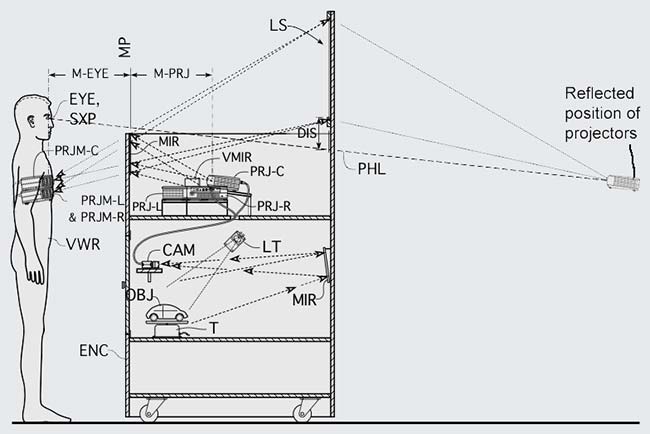
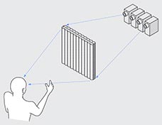
When it’s impractical to mount projectors on the ceiling or the screen on the wall, they can be contained in a cabinet, useful for store displays. The projector’s images are reflected off mirrors so that the optically-equivalent positions of the projectors are at the spacing of the viewer’s eyes.
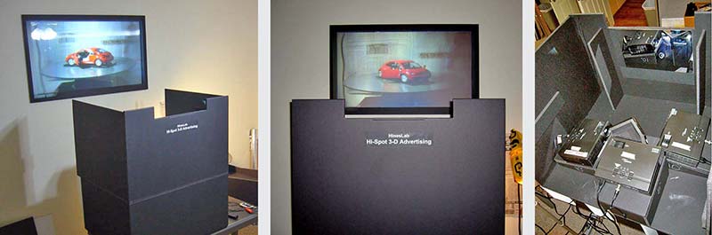
The photos above are not of a finished product, but of a proof-of-concept mockup projecting onto a flat screen on the wall. The photos on the left were shot from a distance to take in the whole scene, however the correct viewing distance is near the front of the cabinet, where the illumination is equally bright across the screen.
Conventional lenticular stereoscopic imaging systems have used two-cameras, and create 2-1/2″-wide viewing positions (exit pupils) of the alternating left and right views. Because our eyes are 2-1/2″ apart, as the viewer moves laterally, they move through the alternating left and right views to see as many reverse-depth views as correct views.
To avoid this problem, this proposal uses narrow exit pupils and additional cameras (or computer-generated views) so that the viewers’ eyes are always receiving images from corresponding camera positions to create natural depth. In other words, the viewer can move laterally and never get a false-depth view.
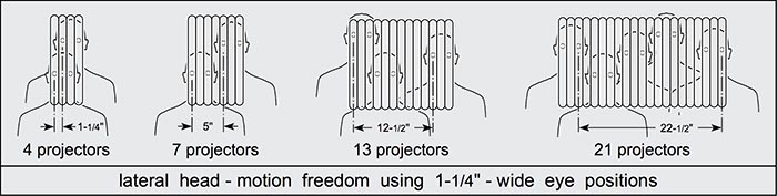
The vertical columns over the faces are exit pupils, or viewing positions, created by the light returned from the lenticular screen. The exit pupils are equal in number to the number of projectors.
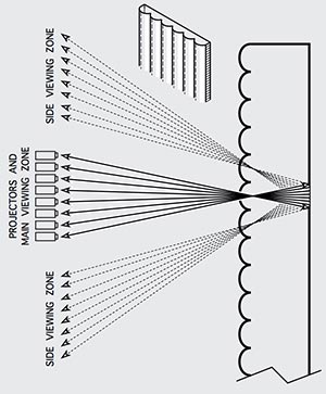 |
| Lenticular displays create additional viewing zones to the sides of the main viewing zone. This has the advantage of increasing the number of viewing positions. The angular position of the side zones is determined by the optics of the lenticular screen, and will limit the number of projectors (so that the viewing zones do not overlap). |
When lenticular screens are molded there may be some warpage due to cool air blowing over an area. The following is a comparison of warped screens when used in front-projection and rear-projection lenticular 3D techniques, and why we propose front-projection.
Front Projection:
|
|
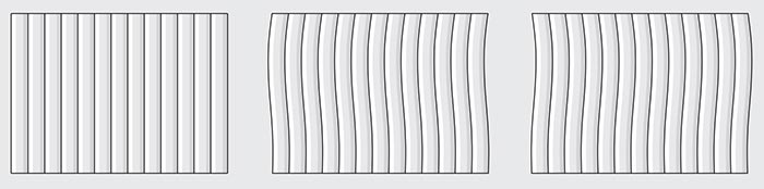 |
| Ideal straight screen Warped but usable screen Warped but usable screen |

In front projection, there is no alignment issue. The projected images automatically form behind the lenticules, even if the screen is severely warped, retro-reflecting the image back to the projector position and viewer at the same distance. The scale and amount of distortion in these drawings is exaggerated for illustration.
Rear Projection:
|
|
|
| Warped lenticular screen Identical screen flipped over Overlaid mis-aligned screens |
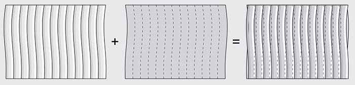
In rear-projection, a diffuser is sandwiched between two sheets of lenticular plastic, placed back to back. Rotation and alignment of the lenticular screens is extremely critical. Warpage of either screen will cause a mis-match of lenticules.
Rear-projection displays need a field lens to brighten the corners of the image. Fresnel lenses are the only practical choice for large screens, however cannot be used with lenticular screens because of the Moire patterns created between the circular grooves of the Fresnel lens and lenticular screens. The diffuser between the lenticular sheets trades off corner brightness to avoid the Moire pattern.
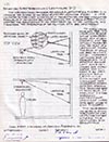
Hines’ original lab notebook entries for this invention:
 |
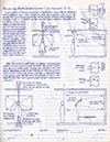 |
| p. 140 | p. 143 |
This is a technology announcement and license offer. This is not a product being offered for sale to end users. HinesLab seeks licensees. Manufacturers are invited to contact Steve Hines to discuss licensing at: