Lensless Copier-Scanner
Lensless Copier-Scanner
This was an investigation by Steve Hines in 1986 to reduce the cost and complexity of office copiers and scanners by using retro-reflective materials instead of image-forming lenses.
Technique #1:
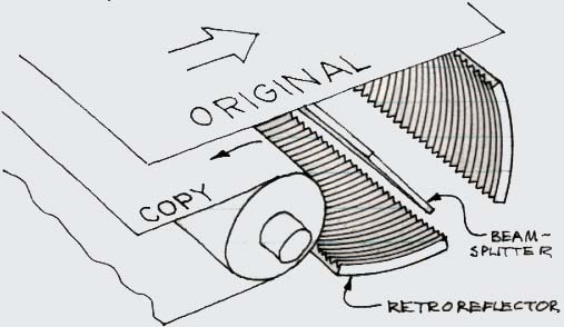
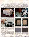
The basic concept uses inexpensive retro-reflective sheet material, and a 45°-beamsplitter to direct light from the original document to the copy surface. Possible arrangements are using the retro-reflector (1) below the beam splitter, (2) beside the beam splitter, or (3) both, to double the brightness.
The mockup held the basic elements, light source, glass copy surface, 45°-beamsplitter, flat sheet of retro-reflector at the bottom, and flat glass at the image-forming surface at the end. The light source is polarized and used at Brewster’s angle to minimize surface reflections.

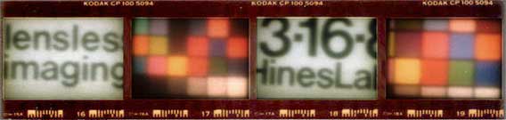
The copier mockup is turned on its side with the “original” image projected onto a frosted screen. The image was internally retro-reflected to a second frosted screen which was taped over the “copy” surface, where it was photographed.
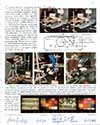
To test the image resolution of the Reflexite corner-cube sheet material, images on 35mm slides were relayed and imaged on unexposed film in a 35mm SLR camera, with its lens removed. All images are reproduced 1:1 size with this technique.
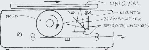
Proposed copier layout using retro-reflector to relay the image of the original document to the light-sensitive drum.
Technique #2:
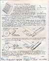
| An alternate technique of forming 1:1-size images uses 3M linear retro-reflector with “V”-shaped grooves on the backside using TIR (Total Internal Reflection), or the grooves could be aluminized for front-surface reflection as shown at right. When the material is flat, it retroreflects in only one direction, orthogonal to the facets; and reflects normally parallel to the grooves, as with normal plane mirrors. The material can be curved to reflect from one line to another as shown below. | 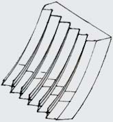 |
The primary advantage of this approach is the 4X brightness increase due to the elimination of the beam splitter. A strip of parallel roof-edge mirrors, formed into an elliptical shape, is placed in a position to relay a line of the original document, at one line focus of the ellipse, to the receiver sheet at the second line focus of the ellipse.
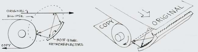
In both techniques the divergence-caused image spread in a plane at right angle to the roof edges, is two times the roof mirror width. To obtain the required 10 lp/mm resolution, for an office copier, the pitch of roof-edge mirrors should be ≤1/20 mm.
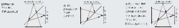
Technique #3:
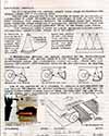
This is a technique for forming images using linear retroreflector material curved into a cylindrical strip. There are two equally desirable configurations, which can be used individually at 25% efficiency, or together to double the efficeincy to 50%.
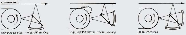
Due to the geometry of a cylinder 1:1 imaging is assured along the line focus of the original, and optically equivalent line focus of the copy.
 |
 |
 |
 |
 |
| p. 46 | p. 47 | p. 49 | p. 50 | p.52 |
Hines’ original laboratory notebook entries for this invention.
This is a technology announcement. Office copier and scanner manufacturers are invited to contact Steve Hines to discuss a manufacturing and sales licensees.
USA
email: Steve@HinesLab.com
ph. 818-507-5812